HFC/J Low Voltage Generators are mainly divided into two categories:
HFC/J6 45、50、56Series and HFC/J5 63、71、80Series
Power: 300KW---5000KW
Pole number: 4、6、8、10
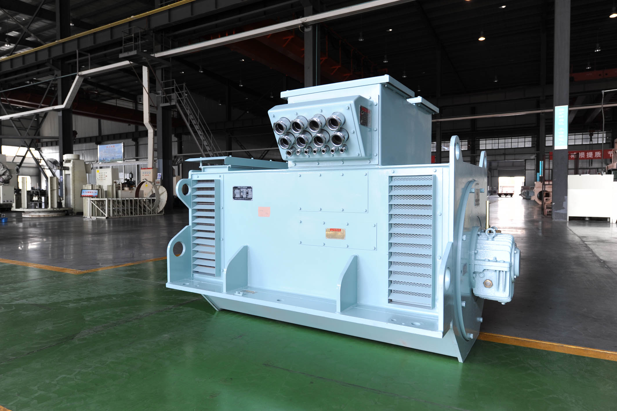
Application The brushless constant voltage synchronous alternator is of a self- excited type with an electronic voltage regulator integrated in the excitation unit.It is used as main and standby units inland based power installations and for marine electrical supplies and can be driven by internal combustion engines,gas or steam and water turbines and electric motors.
Construction The alternator comprises the main machine(revolving field machine with cylindrical rotor and damper winding),exciter(revolving armature machine)and excitation equipment. The excitation power is supplied to the rotor of the main machine via rotating rectifiers.
Excitation System The alternator is fitted according to size and type with an excitation system with THYRIPART excitation system space(load dependent excitation,compounded with thyristor voltage regulator).This method results in excellent dynamic response to load switching applications and short circuits.
Technical Data
●The alternator voltages on our standard design are 400v at 50Hz and 450V 60Hz.
●Power factors from 0.8 to 1(lagging),If the power factor is less than 0.8, the output power is corrected according to the table below.
|
Power factor COSΦ
|
Permissible output % of rated value
|
|
|
HFC5
|
HFC6
|
|
0.8
|
100
|
100
|
|
0.7
|
95
|
96
|
|
0.6
|
91
|
92
|
|
0.5
|
89
|
91
|
|
0.4
|
87
|
90
|
|
0
|
84
|
88
|
●Insulation is class F or H
●Sinusoidal load current
●Symmetrical load
●Apart from an internal reference value potentiometer fitted in the regulator, the rated voltages can be adjusted 5% using a reference value setter to be mounted in an external panel.
●Inquiries are also welcomed for special voltages and for frequencies other than 50Hz or 60Hz
Steady state voltage variation
Throughout the range from no load to rated load at rated power factor, the following voltage regulating accuracies are achieved:
Isolated operation(Without droop compensation device)U±0.5%
Parallel operation (with droop compensation device)U±2.5%
The voltage variation of alternators with droop compensation device can be improved to that of isolated operation value by short circuiting the droop compensation devices, while not in parallel operation.
Parallel operation Active load sharing controlled with the governor of the driving engine.Reactive load sharing assured by a droop compensation device
Protection equipment Protection equipment The stator winding can be provided with thermal protection in the form of PTC sensors or resistance thermometers(optional). Please inquire when alternator protection gear necessitates opening of neutral.Please indicate type designation if it is intended to use a star point current transformer.
HFC/J Series Selection Table of Low Voltage Alternators
HFC/J Series selection table